UGUIDots Progress Report
UGUIDOTS is a data oriented workflow of Unity default runtime UI, UGUI. This provides a conversion workflow to convert the authored GameObject UI to a more DOTS friendly UI system, that works with their Universal Render Pipeline (formerly known as Lightweight Render Pipeline).
While UIElements certainly scales better and a DOTS version is in the works, I wanted to solve my current issues and have a good understanding of the UI Pipeline.
How it came to be?
UGUIDOTS was born from my need to have a much more efficient UI system for mobile and lower end hardware. When demoing Project Arena (now called Carte Diem) at PlayNYC, I noticed that my demo devices were heating up too quickly after short play sessions. This was primarily due to Unity’s auto batching and mesh rebuilding for their UI taking a large slice of the CPU.
So, more work done over extended periods of time means more heat generated. On mobile devices, this can mean a very uncomfortable play session.
Why does this happen?
Well Unity’s UI has a tendency to auto batch common UI elements. The goal behind this is to limit the number of draw calls issued to the GPU. By combining elements together into a single mesh, Unity can send less instructions and upload everything it needs in one as little calls as possible.
This is interesting by design, due to doing the heavy lifting for you but can be flawed. For example, let’s take a simple nested UI with the same material and texture. By design, Unity will batch the hierarchy into 1 draw call. You can see this in the Frame Debugger at Editor or runtime.

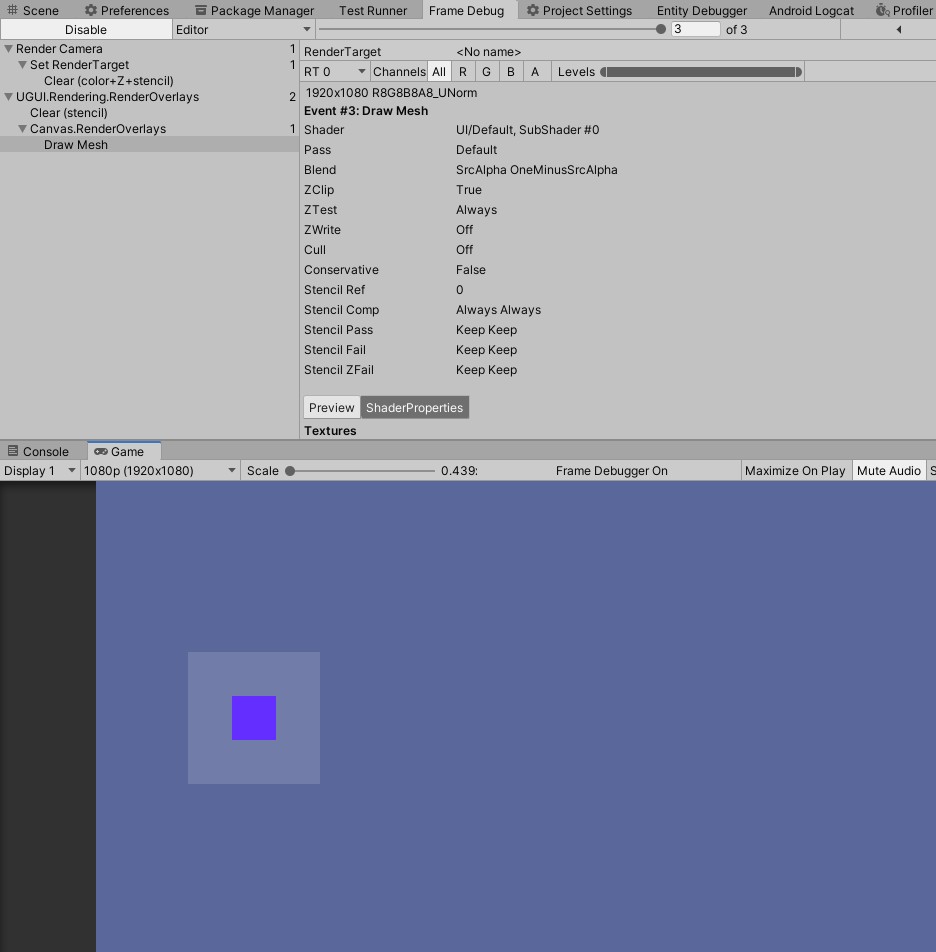
This made me wonder how images moved if there was a single draw call to render all the images. If an image moves, then the whole canvas is marked dirty and rebuilt. Now splitting your UI into smaller canvases is a Unity recommended optimization tip, but it does not solve the underlining issue.
The First Attempt
The first step to building UGUIDOTS was to build a basic image. Typically images will just have 4 vertices and 6 indices as its basic building block, effectively a quad. (I’m selectively ignoring 9 slicing images because I have not yet supported that feature yet).
Instead of batching all the elements together, I left each image to have it’s own draw call. I figure:
instead of just rebatching the UI altogether and recomputing where the new vertices will be, why not just have them drawn individually and update the transformation matrix? This makes the systems much simpler to work with.
The idea was very naive, but it worked. Now my issue was that I was issuing more draw calls than necessary to draw a few simple shapes. After some basic tests and battery usage comparisons, I saw that the idea, while it solved the issue of updating a single element’s position/color, it used way more battery life than I expected (8% app battery usage compared to UGUI’s 5% app usage in 30 minutes).
Ultimately, I had to batch and instruct the same number of draw calls as Unity’s Default UI System to ensure its performance when rendering.
The Second Attempt
There was a question that came to my mind when revisiting the batching issue:
- Should UGUIDOTS automatically handle batching for me as a user?
At the time, all I wanted was to have a joystick UI that was dynamic and followed the finger’s position. Ultimately, I foregoed the idea of runtime batcher because I would effectively be recreating Unity’s UI in DOTS. Instead, it made much more sense to perform static analysis on the hierarchy and embed this information for runtime. Rather than recreate the batch whenever there is a change in the UI, the information is readily available in case there is a need to rebuild and rerender the UI.
Batches
Batches are stored into a few parts…
- An array of rendered elements
- An array of spans, which define which vertices and indices belong to which batch
- An array of spans, which define which entity is associated with which batch
However, there are certainly some limitations in regards to static analysis. Dynamic UI is not as easy as you have to predefine the number of elements early on or manually manipulate the runtime representation of the batch, which can become very messy.
Text, text, text
My biggest gripe with text in C# or even C++, is the string type. There are times when I need immutable string values,
which means that the system implementation of string is good enough for me, but for most intensive purposes, I actually
needed to update the string value.
For example, take a health text you want to update frequently. By constantly reassigning the string variable with a numerical representation, the garbage collector will collect the previous value of the string as it is no longer being used.
For this, I need a mutable string type, which is typically in the form a character array or character pointer. Natively,
string types can be represented through the FixedString types, but I opted to use a DynamicBuffer<CharElement>,
such that
- it is easier to debug in the EntityDebugger
- they can be treated as mutable strings by simply updating an index or resizing the buffer to match the string’s # of chars
Rendering Text
Rendering text is surprisingly simple. Each character is represented by a quad with a series of defined UV coordinates. These UV coordinates are mapped to a font’s generated bitmap texture.
Font files have embedded metrics which can be read to procedurally construct the mesh at specified positions and sizes. Once the current character is finished, advance to the next character by computing the spacing and offset between each letter. The offsetted position then becomes the start position of the next character. This would continue until the current character overshoots the max width of the line. From there, the next character is positioned on the next line.
For a more detailed look of how fonts are generated, the OpenGL tutorial provides a thorough step by step process. The algorithm is actually implemented and adapted in UGUIDOTS using TextMeshPro’s material and to account for relative screen size.
The styling is not exactly the same as Unity’s but similar. Expect bold fonts to look like normal fonts but with less spacing in between compared to Unity’s bold style.
Factoring Width and Counting Lines
Given a dimension, I can find how out how many characters fit within each line of text and the number of lines that a that the entire text will take up, naively. The same algorithm used to generate the mesh at its proper position is the same algorithm used to calculate how many characters fit within each line. This means that the characters are looped twice when the text mesh is being generated to be rendered.
Screen Sizes and Scale
For most of my development purposes, I tend to use the Scale With Screen Space option on the Canvas. This option
allows you to define a reference resolution, and if the screen size is smaller than the reference resolution, the Canvas
scales down. Vice versa if the screen size is much larger than the defined reference resolution.
This follows the same logarithmic scale function Unity’s canvas uses.
log_width  = 2^(log2(width / current_resolution_width))
log_height = 2^(log2(height / current_resolution_height))

scale = lerp(logWidth, logHeight, a_defined_ratio)
The CanvasScalerSystem only handles scaling when the current resolution does not match the previously known reference
resolution, which is currently done through an event system.
Events
Events are currently done using a producer consumer styled system of entities. A system produces a messaging entity with component data that needs to be processed. Due to the detection of that messaging entity with said component, another system will process that entity and perform its operations. Finally, the messaging entities are consumed, so that system no longer runs.
This is implemented into the CanvasScalerSystem because the system should only run if the screen resolution changes.
There is an ECS events developed by jeffvella which builds event queues to publish events at runtime.
Anchoring
Unity’s anchoring system works with relative local spaces. This means that the anchor defined in the inspector is relative to the current element’s parent. See the gif below with a child element that is 150 units away from the upper left hand corner of its parent element.
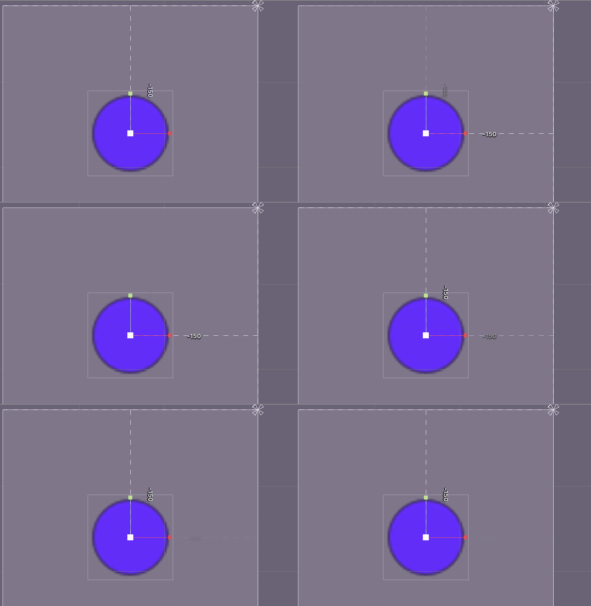
What gets tricky with anchoring is taking the anchor position relative to its parent and computing the new position of the element in a tree like hierarchy. This would be easy if all computed positions are actually applied back to its element, but could potentially cause race conditions when doing this in parallel to other systems. To ensure that the data is correct for parallel systems, the updates to the elements are pushed to a command buffer for the positions to be applied on the next frame.
This was done by iterating over each root Canvas element and recursively computing each child’s new position. The newly computed parent’s world space position is passed onto its children to compute its current local space position. This is similar to how Unity’s current anchor system works with relative distances to their parent’s position.
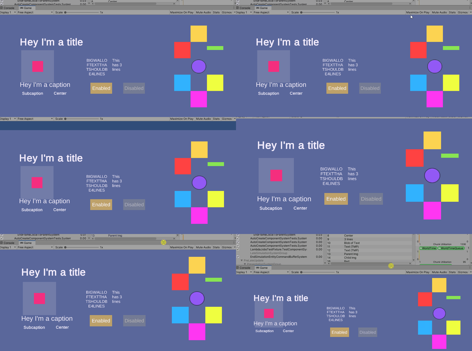
Example of Anchoring and Scaling
Like the CanvasScalerSystem determining the position of the element based on the anchor is done only when the screen
is resized. (I currently don’t see a use in recomputing the anchor outside of a screen resolution change.)
Buttons
I don’t think any UI is really complete without some sort of interactable element. Buttons deviate slightly from how Unity’s UI typically handles them. The current UI uses serialized Unity events. Write a behavior, drag the behavior into the serialized field and select the function that will be executed.
Currently, in UGUIDOTS, buttons are defined with a few additional options. For instance, you can define the click behavior. For most desktop uses, a click behavior of release up makes sense as a click is only registered when the user releases their finger from the mouse. However, for mobile it might make sense to have a button type of press down, meaning that the click is registered to the button the moment their finger touches the screen. Lastly, there is a held button type, which means that a click is continuously registered as long as the button is pressed.
Now, for the more cumbersome details about buttons are custom behaviors. To implement your own custom behavior for the button,
you need to author your own message payload. The message payload is a dummy entity that needs to be constructed as a
template. This follows the same event system that’s used in canvas scaling and anchoring system. A ButtonMessageProducerSystem
will produce a copy of the templated message entity. You would write a system that would process the message entity and
perform any button logic there. (A more cohesive demo will be coming soon.)
With buttons, only the legacy input system has been supported. The new input system will be supported much later down the line.
Translation
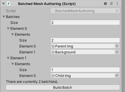
Translation of elements is supported in a different fashion. The world space matrix and local space matrix do get updated, but those do not actually move the mesh. This has been offloaded to a shader which handles translation. To ensure that this works, the movable elements must not be batched, because the shader will move all vertices of the mesh and batched elements have all vertices in the same submesh.
Currently the workflow is a bit cumbersome because the current static analysis workflow is shown as an array of arrays without any kidn of tooling to allow you to redefine the batch. (This is something I intend to work on much later down the pipeline.)
Fill Amounts
To handle fill amounts, instead of manipulating the mesh like what Unity does, I opted to write a shader with incremental clipping support. This means that the mesh does not have to be rebuilt and reuploaded to the GPU as it is no longer marked as “modified” for the next render frame.
An interesting side effect of opting to use a shader with clipping and stencil masks, is that an image’s border will not be clipped from rendering so you can see how much fill is applied without any additional background changes.
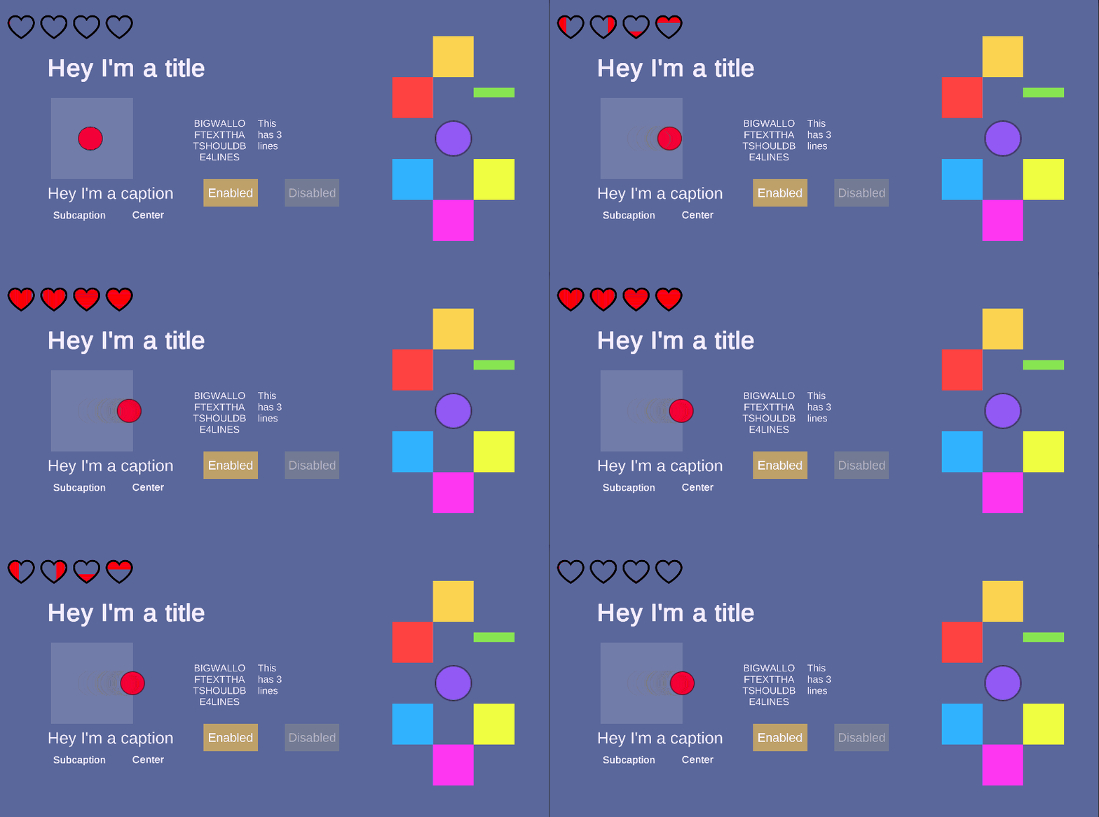
Putting this all together
Once each elements local vertex data is built, the local vertices are copied into the Canvas' vertex and index buffer. The batches that were defined at Editor time now play an important part here. The Canvas entity contains spans which define which part of the vertex and index buffer is part of which submesh. Similarly, it contains mappings to state which entities belong to which batch. Once the children vertices are consolidated into the root Canvas, the mesh is built and uploaded to the GPU.

You can see how canvases on the right side of the hierarchy are destroyed, as the canvases are converted from their GameObject style hierarchy into their entity format.
In some foreseeable future
UGUIDOTS will most likely be maintained to match UGUI’s current existing features. As more needs arise in my own game, I’ll put more updates into UGUIDots. Some of the features I can somewhat expect to develop sometime in the future in no particular order are:
- Multiple Graphics Command Buffers
- World space canvases
- Input fields
- Image slicing
- Layout groups
- Radial fill
- Regressively adding tests (make maintenance of the repo easier)
